Maximum fiber optic range: distances, optical budget and guide by data rate
Contents
The maximum range of a fiber optic cable is not a property of the cable alone — it is the result of a balance between link attenuation and the sensitivity of the active equipment. The same OS2 cable can carry 1 Gbit/s over 100 km with suitable modules, or only 10 Gbit/s over 10 km with standard modules. This guide explains the principles of the optical budget, gives the actual distances by standard and by data rate, and helps you calculate the range of your own installation.
The optical budget: a fundamental concept
The optical budget (or link budget) is the power margin available between the transmitter and the receiver of a fiber link. It is expressed in dB and represents the maximum loss the link can tolerate while maintaining an acceptable error rate (BER ≤ 10⁻¹²).
Optical budget (dB) = Transmit power (dBm) − Receiver sensitivity (dBm) − Safety margin (dB)
Concrete example with a standard 10G SFP+ LR module:
- Typical transmit power: −1 dBm to +3 dBm
- Receiver sensitivity: −14 dBm
- Recommended safety margin: 3 dB (aging, thermal variations)
- → Available budget: (3) − (−14) − 3 = 14 dB
This 14 dB budget must absorb all the losses of the link: cable attenuation, connector losses, fusion splice losses, and the losses of any passive components (couplers, splitters). The maximum range is obtained by dividing the available budget by the cable's attenuation per km:
Max distance (km) = Available budget (dB) ÷ Cable attenuation (dB/km) − [Fixed losses / Cable attenuation]
For an OS2 cable with attenuation of 0.35 dB/km at 1310 nm, 4 connectors (4 × 0.5 dB = 2 dB) and 2 splices (2 × 0.1 dB = 0.2 dB): max distance ≈ (14 − 2 − 0.2) / 0.35 ≈ 33 km.
Distances by IEEE and ITU standard
| Standard | Data rate | Fiber type | Wavelength | Max distance | Module |
|---|---|---|---|---|---|
| 1000BASE-SX | 1 Gbit/s | OM2 / OM3 | 850 nm | 550 m | SFP 1G SX |
| 1000BASE-LX | 1 Gbit/s | OS2 SM | 1310 nm | 10 km | SFP 1G LX |
| 1000BASE-ZX | 1 Gbit/s | OS2 SM | 1550 nm | 80 km | SFP 1G ZX |
| 10GBASE-SR | 10 Gbit/s | OM3 / OM4 | 850 nm | 300 m / 400 m | SFP+ SR |
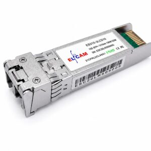
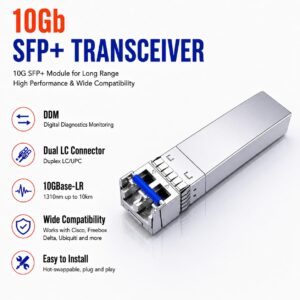
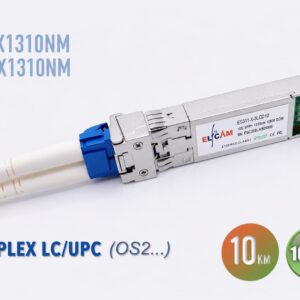
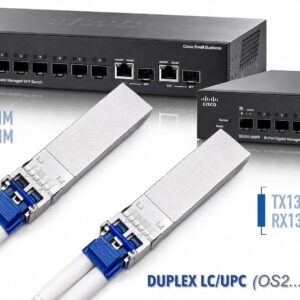
| 10GBASE-LR | 10 Gbit/s | OS2 SM | 1310 nm | 10 km | SFP+ LR |
| 10GBASE-ER | 10 Gbit/s | OS2 SM | 1550 nm | 40 km | SFP+ ER |
| 10GBASE-ZR | 10 Gbit/s | OS2 SM | 1550 nm | 80 km | SFP+ ZR |
| 25GBASE-SR | 25 Gbit/s | OM4 | 850 nm | 100 m | SFP28 SR |
| 25GBASE-LR | 25 Gbit/s | OS2 SM | 1310 nm | 10 km | SFP28 LR |
| 40GBASE-SR4 | 40 Gbit/s | OM3 / OM4 | 850 nm × 4 | 100 m / 150 m | QSFP+ SR4 |
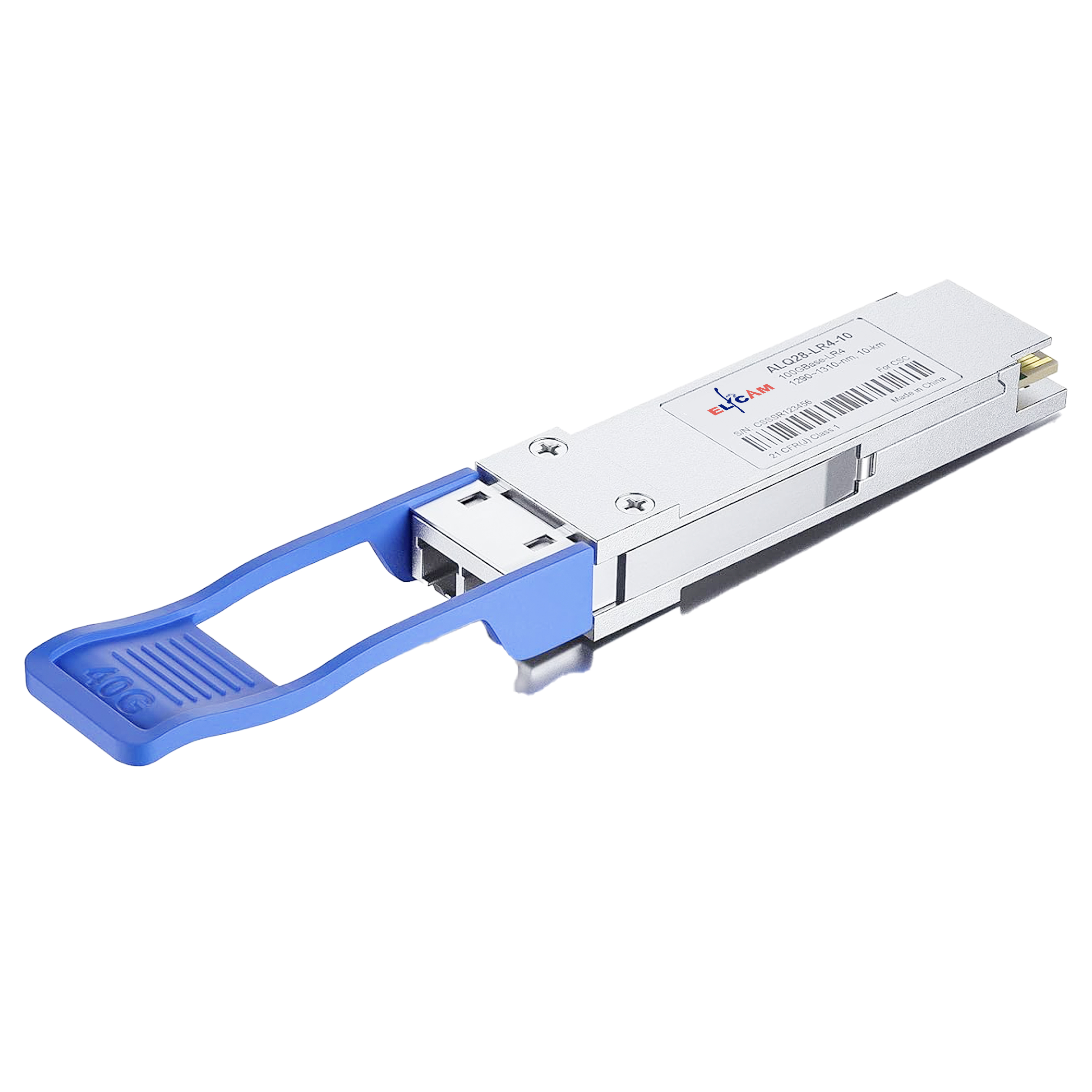
| 40GBASE-LR4 | 40 Gbit/s | OS2 SM | CWDM 4λ | 10 km | QSFP+ LR4 |
| 40GBASE-ER4 | 40 Gbit/s | OS2 SM | CWDM 4λ | 40 km | QSFP+ ER4 |
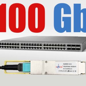
| 100GBASE-SR4 | 100 Gbit/s | OM4 | 850 nm × 4 | 150 m | QSFP28 SR4 |
| 100GBASE-LR4 | 100 Gbit/s | OS2 SM | CWDM 4λ | 10 km | QSFP28 LR4 |
| GPON (ITU G.984) | 2.5 / 1.25 Gbit/s | OS2 SM | 1490 / 1310 nm | 20 km (class B+) | SFP GPON OLT |
| XGS-PON (G.9807.1) | 10 Gbit/s symmetrical | OS2 SM | 1577 / 1270 nm | 20 km (class N2) | SFP+ XGS-PON |
Factors limiting the range
Four physical phenomena cap the maximum distance of a fiber link:
1. Attenuation — this is the dominant factor for short to medium links. Every kilometer of fiber absorbs part of the light power. At 1310 nm, OS2 silica shows 0.35 dB/km; at 1550 nm, only 0.20 dB/km (the lowest-attenuation window). At 850 nm (multimode), the attenuation is 3.5 dB/km — that is 17× higher than single-mode at 1550 nm.
2. Chromatic dispersion (CD) — the different wavelengths making up a light pulse travel at slightly different speeds and arrive offset. This phenomenon broadens the pulses and creates bit errors beyond a certain distance. G.652D fibers have zero dispersion around 1310 nm (~0 ps/nm·km) and high dispersion at 1550 nm (~17 ps/nm·km). For systems at 100 Gbit/s and beyond, dispersion compensation (DCF or digital DSP) is required.
3. Polarization mode dispersion (PMD) — real fibers are not perfectly cylindrical: mechanical birefringence splits each mode into two polarization components that travel at slightly different speeds. Negligible for data rates ≤ 10 Gbit/s, it becomes critical at 40 Gbit/s and beyond over long fibers. Modern G.652D fibers have a PMD ≤ 0.1 ps/√km.
4. Nonlinear effects — at very high optical power (amplified DWDM systems), nonlinear effects appear in the silica (SPM, XPM, FWM). They limit the injectable power and therefore the range on submarine links and long-distance DWDM backbones.
Single-mode OS2: from 10 km to several thousand
Single-mode OS2 fiber (G.652D) is the universal solution for distances greater than 550 m. Its strengths: ultra-low attenuation (0.35 dB/km at 1310 nm, 0.20 dB/km at 1550 nm), no modal dispersion, compatibility with all advanced modulation technologies.
Depending on the transmission system used:
- Direct links without amplification: 10 Gbit/s over 10 km (SFP+ LR), 40 km (ER), 80 km (ZR) with specialized modules
- Amplified links (EDFA): erbium-doped fiber amplifiers compensate for the losses and allow distances of 600–1,000 km between regenerators
- DWDM links: up to 100 wavelengths multiplexed onto a single fiber, each carrying 100 Gbit/s or more, over thousands of kilometers (submarine cables)
- GPON / XGS-PON: 20 km standard (class B+/N2), extended up to 60 km with OLTs with reinforced optical budget (PR30)
Tip: use the 1550 nm window to maximize the range
At equal data rate, a module transmitting at 1550 nm (SFP+ ER/ZR) reaches 1.5× to 2× farther than a 1310 nm module (LR), thanks to the lower attenuation of silica at this wavelength. For an inter-site link between 15 and 80 km, therefore prefer 1550 nm modules over standard 1310 nm modules.

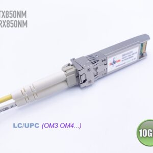
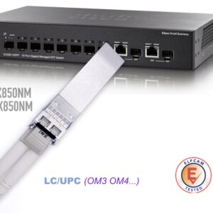


Multimode OM3/OM4: short but economical ranges
Multimode OM3/OM4 fiber is optimized for short, high-density links, typically in datacenters. Its main limitation is modal dispersion: the hundreds of propagation modes broaden each other along the distance, preventing high-rate transmission over more than a few hundred meters.
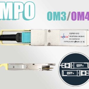
- OM3: 10 Gbit/s over 300 m, 40 Gbit/s over 100 m (MPO-8), 100 Gbit/s over 100 m (MPO-12)
- OM4: 10 Gbit/s over 400 m, 40 Gbit/s over 150 m, 100 Gbit/s over 150 m, 400 Gbit/s over 100 m (MPO-32)
- OM5: 400 Gbit/s via SWDM4 over 150 m (4 wavelengths at 850/880/910/940 nm)
The economic advantage is real: SFP+ SR modules (multimode 850 nm VCSEL) cost 2 to 3× less than SFP+ LR modules (single-mode 1310 nm laser) at equivalent data rate. For a datacenter with hundreds of server-switch links of less than 100 m, the savings are substantial.
Do not overestimate multimode range
The guaranteed distances (OM3: 300 m at 10G) correspond to nominal conditions with clean connectors and a total insertion loss ≤ 3 dB. With worn connectors, tight bends or poor-quality splices, the actual range can be significantly lower. Measure the actual optical budget with an OPM (power meter) before finalizing a critical multimode installation.
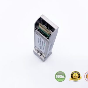
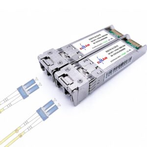
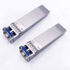
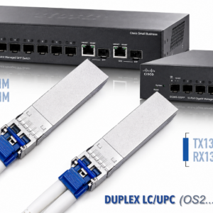
SFP/SFP+/QSFP modules: choosing by distance
The transceiver module is the key component that determines the range. Its choice depends on three parameters: target data rate, available fiber type, distance to cover.

For links up to 80 km without amplification, the ZR/ER modules at 1550 nm offer the best ranges. The Elfcam range includes 40G ZR4 (80 km) and 25G LR (80 km) modules compatible with the main switch brands (Cisco, Arista, Mellanox, HPE, Juniper).
Calculating the maximum range of your installation
Here is the 4-step method to calculate the maximum range of your link:
Step 1 — Note the module specifications: min/max transmit power (dBm) and receiver sensitivity (dBm) in the module's datasheet.
Step 2 — Calculate the gross optical budget: Budget = Min transmit power − Receiver sensitivity
Step 3 — Subtract the fixed losses:
- Connectors: 0.3 to 0.5 dB per connector (conservative budget: 0.5 dB × number of connectors)
- Fusion splices: 0.05 to 0.1 dB per splice
- Safety margin: 3 dB minimum (aging, thermal variations, tolerance)
Step 4 — Divide by the cable attenuation:
- OS2 at 1310 nm: 0.35 dB/km
- OS2 at 1550 nm: 0.20 dB/km
- OM3/OM4 at 850 nm: 3.5 dB/km
If the calculated distance is less than your requirement, several solutions exist: use a module with higher transmit power, switch to a more favorable wavelength window (1550 nm instead of 1310 nm), reduce the number of connectors, or integrate an optical amplifier (EDFA) on the link.
If, on the contrary, the power is too high for your short link (risk of receiver saturation), fixed inline attenuators let you adjust the received power level within the receiver's acceptable range.
1What is the theoretical maximum range of a fiber optic cable?
There is no absolute theoretical limit: with EDFA amplifiers spaced every 80–100 km, submarine DWDM systems carry hundreds of Tbit/s over thousands of kilometers. The submarine link FLAG (Fiber-optic Link Around the Globe) spans 28,000 km. In practice without amplification, the achievable distances are: 550 m (10G multimode OM3), 10 km (10G single-mode LR), 40 km (ER), 80 km (ZR), 120+ km with special modules.
2Can the range of an existing fiber link be increased?
Yes, several approaches: replace the modules with higher-power models (e.g. moving from LR to ER or ZR), change the wavelength from 1310 nm to 1550 nm (40% lower attenuation), reduce the passive losses (cleaning the connectors, replacing worn adapters), or install an EDFA optical amplifier in the middle of the link. Cleaning the connectors alone can recover 1 to 3 dB, that is several additional kilometers.
3What range difference is there between 1310 nm and 1550 nm?
The attenuation of an OS2 fiber is 0.35 dB/km at 1310 nm versus 0.20 dB/km at 1550 nm, that is 40% less attenuation at 1550 nm. With an identical optical budget of 14 dB (typical module budget) and 2 dB of fixed losses (connectors, splices), the range goes from ~34 km at 1310 nm to ~60 km at 1550 nm. This is why long-distance systems systematically use the 1550 nm window.
4Can a multimode fiber optic cable transmit over 10 km?
No, in practice. The modal dispersion of multimode fibers limits the range to a few hundred meters for data rates of 10 Gbit/s and beyond. At 1 Gbit/s, an OM3 fiber can technically reach 1,000 m — but at 10 km, the attenuation losses (3.5 dB/km × 10 km = 35 dB) far exceed the available optical budget. For 10 km, always use single-mode OS2 fiber with SFP+ LR modules.
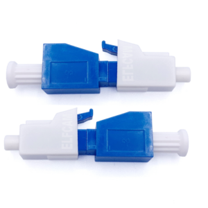
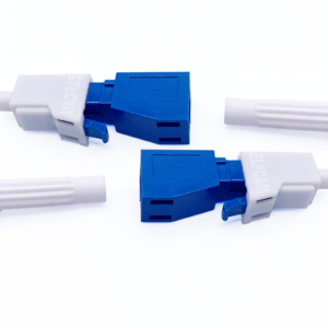
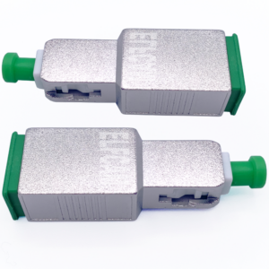
5What is an optical attenuator used for on a fiber link?
On a very short link (a few meters to a few hundred meters), the received optical power can exceed the receiver's sensitivity range, causing its saturation and bit errors. A fixed inline attenuator (1, 2, 3, 5, 10, 15 dB) inserts a calibrated loss to bring the received power back within the acceptable range. Elfcam attenuators are available in LC/UPC, SC/APC and FC/PC connectors in fixed or variable versions.
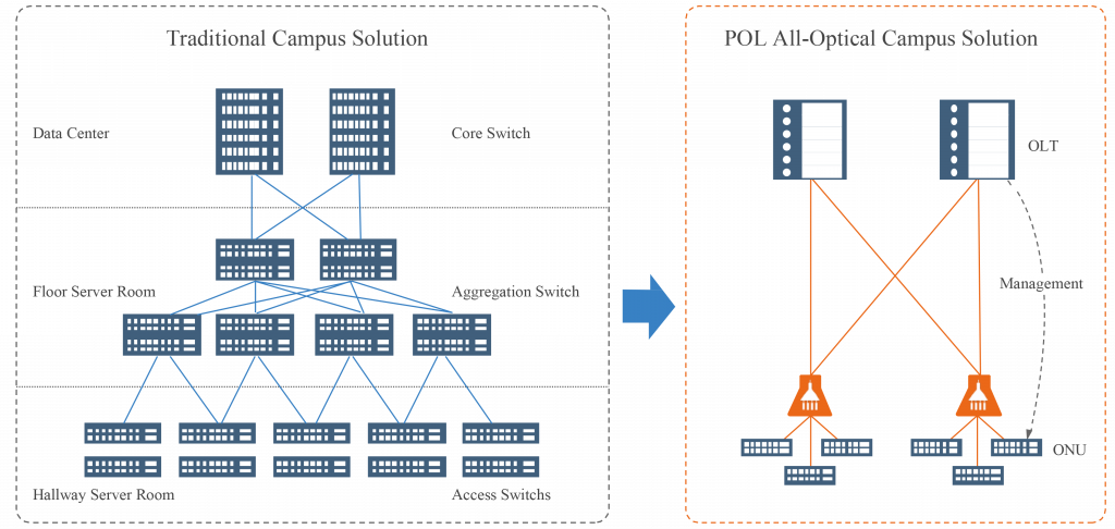
6What is the maximum range of GPON in an FTTH network?
The GPON class B+ standard (ITU G.984) specifies a maximum range of 20 km between the OLT and the most distant ONU, with an optical budget of 28 dB. This budget absorbs the losses of the distribution cable, the splices and the PLC splitters (typically 15–18 dB for a 1:32). XGS-PON (G.9807.1, class N2) offers a similar budget at 10 Gbit/s. Extended-budget OLTs (PR30 = 30 dB) make it possible to reach up to 60 km or higher split ratios.
7How to measure the actual losses of a fiber link?
Two complementary methods: the OPM (optical power meter) + light source measures the total end-to-end insertion loss (insertion method, according to IEC 61280-4-1). The OTDR (optical reflectometer) locates each fault along the path — splice, connector, break — with their position and individual attenuation. The OTDR method is mandatory for FTTH operator certifications and telecom jobsites.
8What are the lead times to receive Elfcam long-range SFP modules?
The SFP+ LR (10G/10 km), SFP28 LR (25G/10 km), QSFP+ LR4 (40G/10 km) and QSFP28 LR4 (100G/10 km) modules are available in stock in France with shipping within 24h. The long-range modules (ER/ZR, 40–80 km) and the optical attenuators are also in stock. Compatible with Cisco, Arista, Mellanox/Nvidia, HPE, Juniper, Marvell and Freebox Ultra equipment. Express delivery available for urgent projects.